
Corvette
Klubbmedlem
-
Blev forummedlem
-
Senaste besök
Allt skrivet av Corvette
-
 Jag håller med dig, hade Steeda burkar på min 06:a och det var sån drone vid 110 så plomberna lossnade så det blev byte Det skall låta utanför bilen och inte i bilen
 -
kostigt att den funkar så dåligt när denna enhet från dem får bra betyg 🤔 https://www.amazon.se/DYNAVIN-2010-2014-bilradio-D8-MST2010-Pro/dp/B087LS2H8S#customerReviews
-
oj de var inte mycket som var ok där inte 😳
-
vad hade den personen skrivit för anledning som gett systemet underkännt i recensioner?
-
Borla brukar vara kännt för att inte ha Drone i sina dämpare https://www.americanmuscle.com/borla-s-axleback-2005-gt.html#customer_reviews
-
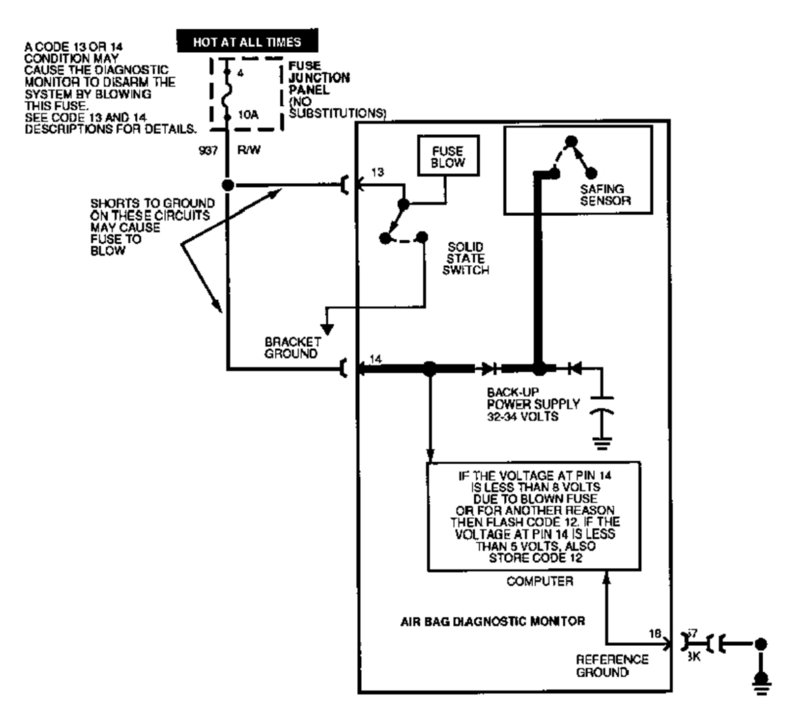
har du kollat säkring nr 4?
-
var i landet är du?
-
Symptom Chart — Driveline Symptom Chart — Driveline Condition Possible Sources Action Traction-Lok does not work in snow, mud or on ice Differential CARRY OUT the Traction-Lok Differential Operation Check in this section. REPAIR as necessary. REFER to Section 205-02B. Lubricant leaking from the pinion seal, axle shaft oil seals or support arm to the housing Vent Damage in the seal contact area or dust slinger on the pinion flange dust shield CLEAN the axle housing vent. INSTALL a new pinion flange and the pinion seal if damage is found. Differential side gears/pinion gears are scored Insufficient lubrication INSTALL new gears. REFER to Section 205-02A or Section 205-02B. FILL the axle to specification. Incorrect or contaminated lubricant type INSTALL new gears. REFER to Section 205-02A or Section 205-02B. CLEAN and REFILL the axle to specification. Axle overheating Lubricant level too low CHECK the lubricant level. FILL the axle to specification. Incorrect or contaminated lubrication type INSPECT the axle for damage. REPAIR as necessary. CLEAN and REFILL the axle to specification. Bearing preload adjusted too tight CHECK the ring and pinion for damage. INSPECT the ring and pinion wear pattern. ADJUST the preload as necessary. Excessive gear wear INSPECT all the axle gears for wear or damage. INSTALL new components as necessary. Incorrect ring gear backlash INSPECT the ring gear for scoring. INSPECT the ring and pinion wear pattern. ADJUST the ring gear backlash as necessary. Broken gear teeth on the ring gear or pinion Overloading the vehicle INSTALL a new ring and pinion. REFER to Section 205-02A or Section 205-02B. Gray or milky axle lubricant in low mileage vehicles Marking compound in axle fluid Inspect axle housing and vent for damage or leaks. Refer to Axle Fluid Analysis in this section. Symptom Chart — NVH Symptom Chart — NVH Condition Possible Sources Action NOTE: NVH symptoms should be identified using the diagnostic tools that are available. For a list of these tools, an explanation of their uses and a glossary of common terms, refer to Section 100-04. Since it is possible any one of multiple systems may be the cause of a symptom, it may be necessary to use a process of elimination type of diagnostic approach to pinpoint the responsible system. If this is not the causal system for the symptom, refer back to Section 100-04 for the next likely system and continue diagnosis. Axle howling or whine Axle lubricant low CHECK the lubricant level. FILL the axle to specification. REFER to Section 205-02A or Section 205-02B. Tuned dampers missing or incorrectly installed REFER to the TSB and follow the procedure outlined. Axle housing damage INSPECT the axle housing for damage. REPAIR or INSTALL a new axle as necessary. REFER to Section 205-02A or Section 205-02B. Damaged or worn wheel hub bearings CHECK for abnormal rear wheel bearing play or roughness. INSTALL a new wheel bearing as necessary. REFER to Section 205-02A or Section 205-02B. Damaged or worn differential ring and pinion INSPECT and INSTALL a new differential ring and pinion as necessary. REFER to Section 205-02A or Section 205-02B. Damaged or worn differential side or pinion bearings INSPECT and INSTALL new differential side or pinion bearings as necessary. REFER to Section 205-02A or Section 205-02B. Driveline clunk — loud clunk when shifting from REVERSE to DRIVE Incorrect axle lubricant level CHECK the lubricant level. FILL the axle to specification. REFER to Section 205-02A or Section 205-02B. Excessive backlash in the axle CHECK the ring gear backlash. REPAIR as necessary. REFER to Section 205-02A or Section 205-02B. Damaged or worn pinion bearings REPAIR or INSTALL new pinion bearings as necessary. REFER to Section 205-02A or Section 205-02B. Damaged or worn U-joints INSPECT the U-joints for wear or damage. INSTALL new U-joints or driveshaft as necessary. REFER to Section 205-01. Driveline clunk — occurs as the vehicle starts to move forward following a stop Worn driveshaft CV joint or U-joints INSPECT the CV joint and U-joints for wear. INSTALL a new driveshaft or U-joints as necessary. REFER to Section 205-01. Loose axle mount CHECK the axle for loose bolts. TIGHTEN to specification. REFER to Section 205-02A or Section 205-02B. High pitched chattering — noise from the axle when the vehicle is turning Incorrect or contaminated lubricant CHECK the vehicle by driving in tight circles (5 clockwise, 5 counterclockwise). FLUSH and REFILL with the specified rear axle lubricant and friction modifier as necessary. Damaged or worn differential (differential side gears and pinion gears) REPAIR or INSTALL new differential side gears or pinion gears as necessary. REFER to Section 205-02A or Section 205-02B. Rumble or boom — noise occurs at coast/deceleration, usually driveshaft speed-related and noticeable over a wide range of speeds Excessive driveshaft runout and/or driveshaft is out-of-balance CHECK the driveshaft runout and balance. REFER to Driveshaft Runout and Balancing in this section. Binding or seized U-joints ROTATE the driveshaft and CHECK for binding or seized U-joints. INSTALL new U-joints or driveshaft as necessary. REFER to Section 205-01. Grunting — normally associated with a shudder experienced during acceleration from a complete stop Binding driveshaft CV joint INSPECT the driveshaft CV joint for binding. INSTALL a new driveshaft as necessary. REFER to Section 205-01. Loose axle mount bolts or suspension fasteners INSPECT the rear suspension and axle. TIGHTEN the fasteners to specification. REFER to Section 205-02A or Section 205-02B. Howl — can occur at various speeds and driving conditions. Affected by acceleration and deceleration Incorrect ring and pinion contact, incorrect bearing preload or gear damage INSPECT and REPAIR as necessary. REFER to Section 205-02A or Section 205-02B. Chuckle — heard at coast/deceleration. Also described as a knock Incorrect ring and pinion contact or damaged teeth on the coast side of the ring and pinion INSPECT and REPAIR as necessary. REFER to Section 205-02A or Section 205-02B. Knock — noise occurs at various speeds. Not affected by acceleration or deceleration Gear tooth damage to the drive side of the ring and pinion INSTALL a new ring and pinion. REFER to Section 205-02A or Section 205-02B. Scraping noise — a continuous low pitched noise starting at low speeds Worn or damaged pinion bearings INSPECT and REPAIR or INSTALL new pinion bearings. REFER to Section 205-02A or Section 205-02B. Driveline shudder — occurs during acceleration from a slow speed or stop Incorrect transmission crossmember orientation CHECK for correct orientation. REINSTALL if necessary. REFER to Section 502-00. Center bearing spacer missing or incorrectly installed CHECK for correct installation of center bearing spacer. REFER to Section 205-01. Drive axle assembly mispositioned CHECK the axle mounts and the rear suspension for damage or wear. REPAIR as necessary. REFER to Section 205-02A or Section 205-02B. Loose axle bolts CHECK the axle for loose bolts. TIGHTEN the bolts to specification. REFER to Section 205-02A or Section 205-02B. Driveline angles out of specification CHECK for correct driveline angles. REFER to Driveline Angle Measurement in this section. For vehicles equipped with a 2 piece driveshaft, ADJUST the driveline angle as neccesary. REFER to Driveline Angle Adjustment In this section. U-joints binding or seized ROTATE the driveshaft and CHECK for binding or seized U-joints. INSTALL new U-joints or driveshaft as necessary. REFER to Section 205-01. Binding or damaged driveshaft CV joint INSPECT the driveshaft CV joint for binding or damage. INSTALL a new driveshaft as necessary. REPAIR as necessary. REFER to Section 205-01. Driveline vibration — occurs at cruising speeds Missing weights or damage to driveshaft INSPECT the driveshaft. INSTALL a new driveshaft as necessary. REFER to Section 205-01. Worn U-joints CHECK for wear or incorrect seating. INSTALL new U-joints or driveshaft as necessary. REFER to Section 205-01. Misalignment of yellow dot on driveshaft-to-yellow dot on pinion flange plus or minus 1 bolt hole REINSTALL driveshaft with yellow dots aligned plus or minus 1 bolt hole. REFER to Section 205-01. Worn or damaged driveshaft center bearing support CHECK the insulator for damage or wear. ROTATE the driveshaft and CHECK for rough operation. INSTALL a new driveshaft as necessary. REFER to Section 205-01. Loose axle pinion flange bolts INSPECT the axle pinion flange. TIGHTEN the pinion flange bolts to specification. REFER to Section 205-01. Excessive axle pinion flange runout CHECK the pinion flange runout. REPAIR as necessary. REFER to Pinion Flange Runout Check in this section. Excessive transmission flange runout CHECK the transmission flange runout. REPAIR as necessary. REFER to Specification in this section. Binding or damaged driveshaft CV joint INSPECT the driveshaft CV joint for binding or damage. INSTALL a new driveshaft as necessary. REFER to Section 205-01. Excessive driveshaft runout and/or driveshaft out-of-balance CHECK the driveshaft runout and balance. REFER to Driveshaft Runout and Balancing in this section. Driveline angles out of specification CHECK for correct driveline angles. REPAIR as necessary. REFER to Driveline Angle Measurement in this section. Transmission mount not centered NEUTRALIZE the transmission mount. REFER to the Transmission Crossmember procedure in Section 502-00. Axle Fluid Analysis The appearance of milky or gray axle fluid in early mileage axles is a result of white marking compound used at the assembly plant to verify gear mesh contact pattern. The marking compound within the fluid will darken some over time. The milky fluid appearance will diminish and cause no harm and does not require a fluid change. Analysis of Leakage Clean up the leaking area enough to identify the exact source. A plugged axle housing vent can cause excessive pinion seal lip wear due to internal pressure buildup. Verify the lubricant level is at specification. Axle Vent A plugged vent will cause excessive seal lip wear due to internal pressure buildup. If a leak occurs, check the vent. If the vent cannot be cleared, install a new vent. Drive Pinion Seal Leaks at the drive pinion seal originate from the following causes: Damaged seal Worn seal journal surface Any damage to the seal bore (dings, dents, gouges or other imperfections) distorts the seal casing and allows leakage past the outer edge of the drive pinion seal. The drive pinion seal can be torn, cut or gouged if it is not installed correctly. The spring that holds the drive pinion seal against the pinion flange may be knocked out and allow fluid to pass the lip. Metal chips trapped at the sealing lip can cause oil leaks. These can cause a wear groove on the drive pinion flange and result in pinion seal wear. When a seal leak occurs, install a new drive pinion seal and check the vent to make sure it is clean and free of foreign material. A new drive pinion flange must be installed if any of these conditions exist. Drive Pinion Nut NOTICE: Install the drive pinion nut to the correct torque specifications or damage to the differential components may occur. On some high-mileage vehicles, oil may leak through the threads of the drive pinion nut. This condition can be corrected by installing a new nut and applying threadlock on the threads and nut face. Differential Seals NOTICE: When installing shafts, do not allow splines to contact seals during installation or damage to the seals may occur. Axle shaft housing seals are susceptible to the same types of damage as drive pinion seals if incorrectly installed. The seal bore must be clean and the lip handled carefully to avoid cutting or tearing it. The seal journal surface must be free of nicks, gouges and rough surface texture. For information on differential seals, refer to Section 205-02A or Section 205-02B. Component Tests Traction-Lok Differential Operation Check A Traction-Lok differential can be checked for correct operation without removing it from the rear axle housing. Raise and remove only one rear wheel. Install the Differential Gauge on the wheel bolts. Use a torque wrench with the capacity of at least 271 Nm (200 lb-ft) to rotate the axle shaft. Make sure that the transmission is in NEUTRAL, and that one rear wheel is on the floor while the other rear wheel is raised off the floor. The breakaway torque required to start rotation must be at least 27 Nm (20 lb-ft). The initial breakaway torque may be higher than the continuous turning torque. The axle shaft must turn with even pressure throughout the check without slipping or binding. If the torque reading is less than specified, check the differential case for incorrect assembly. Traction-Lok Differential Check Road Test Place one wheel on a dry surface and the other wheel on ice, mud or snow. Gradually open the throttle to obtain maximum traction prior to break away. The ability to move the vehicle demonstrates correct performance of a Traction-Lok rear axle assembly. When starting with one wheel on an excessively slippery surface, a slight application of the parking brake may be necessary to help energize the Traction-Lok feature of the differential. Release the brake when traction is established. Use light throttle on starting to provide maximum traction. If, with unequal traction, both wheels slip, the limited slip rear axle has done all it can possibly do. In extreme cases of differences in traction, the wheel with the least traction may spin after the Traction-Lok has transferred as much torque as possible to the non-slipping wheel. Tooth Contact Pattern Check — Gearset To check the gear tooth contact, paint the gear teeth with the special marking compound. A mixture that is too wet will run and smear; a mixture that is too dry cannot be pressed out from between the teeth. Use a box wrench on the ring gear bolts as a lever to rotate the ring gear several complete revolutions in both directions or until a clear tooth contact pattern is obtained. Certain types of gear tooth contact patterns on the ring gear indicate incorrect adjustment. Incorrect adjustment can be corrected by readjusting the ring gear or the pinion. Contact Pattern Location In general, desirable ring gear tooth patterns must have the following characteristics: Drive pattern on the drive side ring gear well centered on the tooth. Coast pattern on the coast side ring gear well centered on the tooth. Clearance between the pattern and the top of the tooth. No hard lines where the pressure is high. Acceptable Ring Gear Tooth Patterns For All Axles Correct Backlash With a Thinner Pinion Position Shim Required Correct Backlash With a Thicker Pinion Position Shim Correct the Pinion Position Shim That Requires a Decrease in Backlash Correct Pinion Position Shim That Requires an Increase in Backlash
-
Skulle ta ner kåpan och kika in, innan jag häller i ny olja. Ljudet du beskriver låter mycket udda, samt att det inte där hela tiden. Wiii pinjong lager Woo hjullager Inga dubbla svarta sträck vid burn, diffen
-
nä de e fram
-
eller så måste de droppa priset för ingen vill köra bensinbil 🤔 Corvetten blir ju helt eldriven nästa år och ingen verkar ju gå mot strömmen i elbilsproduktionen
-
vi tar 375 för slipning och 995 för programmering
-
helt ok, inte det som låter kolla krängsstaget bak samt länkarna till detta om du har ett justerbart panhardstag, kolla att det är ihopsatt korrekt
-
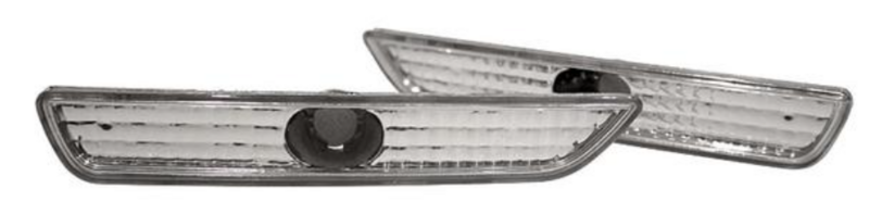
mecka dit dessa så är det snyggare

-
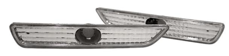
tycker de var hårda när du nu har p-ljus i skenan fram men med fel färg.
-
E85 funkar att få ner CO men inte HC.
-
körde besiktningsmannen dem riktigt varma? man brukar ju få värma dem ganska bra innan racekattar funkar
-
det var ju inte dyrt
-
vad är kostnaden för försäkring på elbilen?
-
Du får åka till Kraftgatan och klämma Hedemora Bilforum på pulsen 😉
-
Ja är sensorn död kommer den inte visa tryck där. Du får göra som Darkis skrev och se om det löser det. (Din bil är ju på gärdsgården med garantin, man har ju 5 år på svensålda Mustanger.)
-
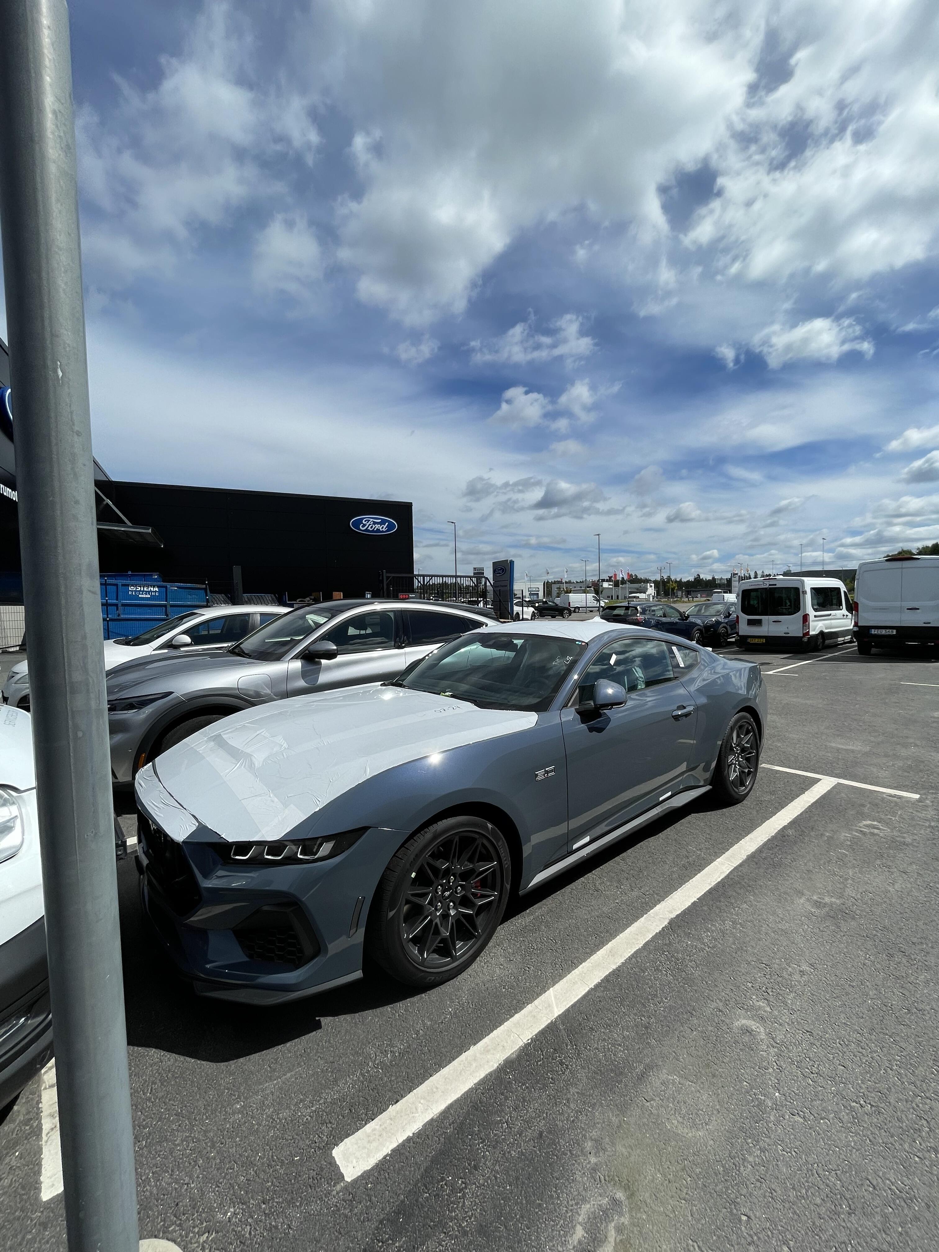
Grattis till en snygg bil 👍
-
batteriet i fobben då? har du prövat att lägga den i mugghållaren med avkänningen i ?
-
Den skall funka https://www.ebay.com/itm/361652078253
-
Ja de är pålitliga, eftersom vi har Mustang kan jag ju inte säga att den är bättre Men klart bättre som familjebil än Mustangen kan jag ju säga utan att bli avrättad 😅